Nut Insert Round Body Reduced Flange Technical Datasheet
Open and Closed End
Product Overview
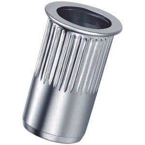
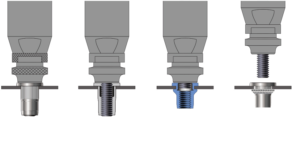
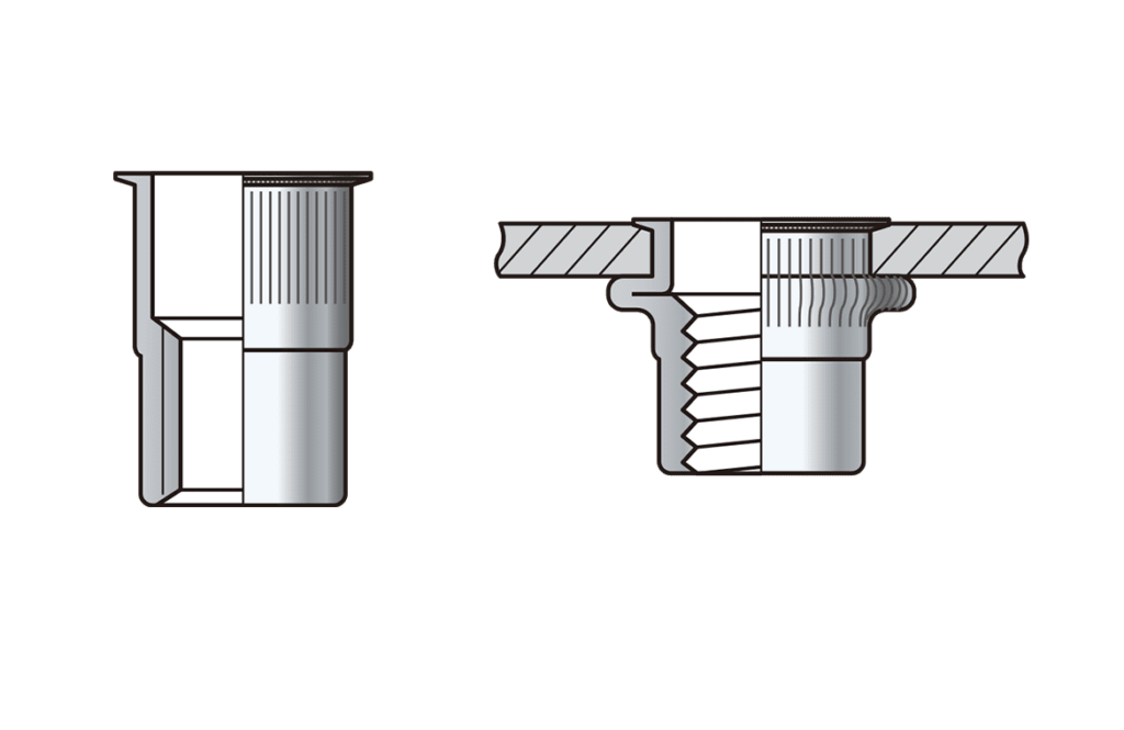
Round Body Reduced Flange Nut Inserts provide strong, reusable internal threads in thin sheet materials where access is available from only one side. The reduced flange design offers a lower-profile installation than large flange inserts while still providing sufficient bearing surface for secure fastening. The round body expands during installation to create a permanent mechanical lock in the parent material.
This datasheet covers both Open End and Closed End variants, manufactured in Steel (Zinc Plated) and Stainless Steel, and provides dimensional data, technical specifications, material options, and application guidance for engineering and manufacturing applications.
Table of Contents
Standards
Manufacturers Standard
Installation
Dimensions
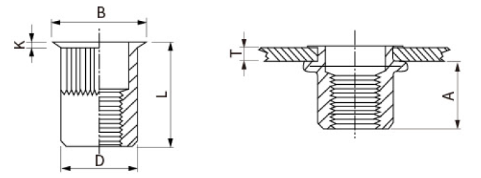
Open End Round Body Reduced Flange Nut Insert
ITEM CODE: 4052
Open End Nut Inserts allow screws or threaded rods to pass completely through the insert, making them suitable for through-hole assemblies and applications requiring longer fasteners.
| Size | Grip Range | A | Hole Size +0.1 | D +0.07, -0.1 | B | K | L |
|---|---|---|---|---|---|---|---|
| M3 – Gr 1 | 0.5-2.0 | 6 | 5 | 4.9 | 6 | 0.5 | 9 |
| M3 – Gr 2 | 1.5-3.0 | 11.5 | |||||
| M4 – Gr 1 | 0.5-2.0 | 7 | 6 | 5.9 | 7 | 0.5 | 11.2 |
| M4 – Gr 2 | 2.0-4.0 | 13 | |||||
| M5 – Gr 1 | 0.5-2.0 | 7 | 7 | 6.9 | 8 | 0.5 | 11.5 |
| M5 – Gr 2 | 2.0-4.0 | 13 | |||||
| M6 – Gr 1 | 0.5-2.5 | 8.5 | 9 | 8.9 | 10 | 0.6 | 14 |
| M6 – Gr 2 | 2.5-5.0 | 16 | |||||
| M8 – Gr 1 | 0.5-30 | 10 | 11 | 10.9 | 12 | 0.65 | 16.5 |
| M8 – Gr 2 | 3.0-5.0 | 18.5 | |||||
| M10 – Gr 1 | 1.0-3.5 | 12.5 | 13 | 12.9 | 14 | 0.7 | 19.5 |
| M10 – Gr 2 | 3.5-6.0 | 22 | |||||
| M12 – Gr 1 | 1.0-4.0 | 16.2 | 16 | 14.9 | 17.6 | 0.75 | 24.2 |
| M12 – Gr 2 | 4.0-6.5 | 0.8 | 27.5 |
Closed End Round Body Reduced Flange Nut Insert
ITEM CODE: 4059
Closed End Nut Inserts feature a sealed bottom that prevents screw penetration beyond the insert. They are ideal where moisture, dust, oil, or contaminants must be prevented from entering the assembly or where blind fastening is required.
| Size | Grip Range | A | Hole Size +0.1 | D +0.07, -0.1 | B | K | L |
|---|---|---|---|---|---|---|---|
| M4 – Gr 1 | 0.5-2.0 | 11 | 6 | 5.9 | 7 | 0.5 | 15 |
| M4 – Gr 2 | 2.0-3.5 | 16.5 | |||||
| M5 – Gr 1 | 0.5-2.0 | 12.5 | 7 | 6.9 | 8 | 0.5 | 16.5 |
| M5 – Gr 2 | 2.0-3.5 | 18 | |||||
| M6 – Gr 1 | 0.5-3.0 | 15.5 | 9 | 8.9 | 10 | 0.6 | 20.5 |
| M6 – Gr 2 | 3.0-4.5 | 22 | |||||
| M8 – Gr 1 | 0.5-3.0 | 17 | 11 | 10.9 | 12 | 0.65 | 23 |
| M8 – Gr 2 | 3.0-4.5 | 24.5 | |||||
| M10 – Gr 1 | 1.0-3.0 | 18.2 | 13 | 12.9 | 14 | 0.7 | 24.5 |
| M10 – Gr 2 | 3.0-5.0 | 26 | |||||
| M12 – Gr 1 | 1.0-4.0 | 20 | 16 | 15.9 | 17.6 | 0.8 | 29 |
| M12 – Gr 2 | 3.0-6.0 | 32 |
all dimensions in mm
Material Characteristics and Recommended Applications
| Material | Characteristics | Typical Applications |
|---|---|---|
| Steel Zinc Plated | High strength, economical, suitable for indoor environments | Industrial equipment, electrical panels, machinery |
| Stainless Steel A2 | Excellent corrosion resistance and strength | Food equipment, marine, outdoor enclosures, pharmaceutical machinery |
Technical Specifications
| Property | Specification |
|---|---|
| Product Type | Blind Rivet Nut |
| Body Style | Round Body |
| Flange Style | Reduced Flange |
| End Style | Open End / Closed End |
| Thread Type | ISO Metric |
| Installation | Blind Installation |
| Material Options | Steel, Stainless Steel |
| Finish (Steel) | Zinc Plated |
| Finish (SS) | Plain Passivated |
| Installation Tool | Manual, Pneumatic, Hydraulic |
| Recommended Materials | Steel, Stainless Steel, Aluminium, Composite Panels |
Applications
- Sheet Metal Fabrication
- Electrical Control Panels & Enclosures
- Datacentres
- HVAC Equipment
- Telecommunications Cabinets
- Data Centre Infrastructure
- Automotive Components
- Commercial Vehicles
- Furniture Manufacturing
- White Goods & Appliances
- Signage
- Solar Equipment
- General Industrial Fabrication
Advantages
- Blind installation from one side of the workpiece
- Provides strong reusable internal threads
- Reduced flange offers a cleaner, lower-profile appearance
- Suitable for thin sheet materials
- No welding required
- Fast installation with standard nut insert tools
- Excellent pull-out and spin-out resistance when correctly installed
- Available in both open and sealed end configurations
- Compatible with steel, stainless steel, aluminium and other sheet materials
- Available in steel and stainless steel for various environmental conditions
Frequently Asked Questions
What is the difference between Open End and Closed End Nut Inserts?
An Open End Nut Insert allows the screw to pass completely through the insert, making it suitable for through-hole applications. A Closed End Nut Insert has a sealed bottom that prevents screw penetration and helps protect the assembly from moisture, dust, and contaminants.
When should I choose a Reduced Flange instead of a Large Flange?
Reduced Flange Nut Inserts are preferred when a lower-profile head is required while still providing adequate bearing surface. Large Flange versions offer greater pull-through resistance on softer materials.
Can these inserts be installed from one side?
Yes. Round Body Reduced Flange Nut Inserts are blind fasteners and require access from only one side of the workpiece.
What materials are available?
They are commonly manufactured in zinc-plated steel and stainless steel.
What installation tool is required?
A manual, pneumatic, battery-operated, or hydraulic nut insert installation tool can be used depending on production volume.
Can these inserts be used in stainless steel sheets?
Yes, provided the correct hole size, grip range, and installation force are used.
Need Technical Assistance or a Quote?
Looking for pricing, samples, CAD drawings, or help selecting the right fastener? Our team can help you choose the correct product for your application.
📧 sales@horizonincindia.com | 📞 +91 80 4117 9152 | 💬 +91 99167 77262
Related Products
Technical Disclaimer
The technical information, specifications, dimensions, mechanical properties, drawings, and performance data provided on this website are intended for general reference and engineering guidance only. Values shown are representative of products manufactured under normal production conditions and may vary depending on material grade, manufacturing tolerances, installation method, application, and operating environment.
While Horizon Inc. makes every reasonable effort to ensure the accuracy of the information provided, we make no warranties, express or implied, regarding its completeness, accuracy, or suitability for any particular purpose. Customers are responsible for verifying that the selected product is appropriate for their specific application and operating conditions. Where safety, structural integrity, or regulatory compliance is critical, independent engineering evaluation and product testing should be performed.
Horizon Inc. reserves the right to modify product specifications, dimensions, materials, and technical data without prior notice.
To the fullest extent permitted by applicable law, Horizon Inc. shall not be liable for any direct, indirect, incidental, consequential, or special damages arising from the use of, or reliance upon, the information contained on this website.
Copyright
© 2026 Horizon Inc. All Rights Reserved.
All content, product data, specifications, technical drawings, images, and documents published on this website are the property of Horizon Inc. and may not be reproduced, distributed, modified, or transmitted without prior written permission.