Arc Weld Stud ISO 13918 RD Technical Datasheet
Reduced Diameter Arc Weld Stud for Industrial and Structural Applications
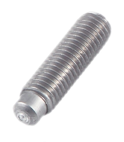
ISO 13918 RD weld studs are reduced diameter arc weld studs designed for permanent attachment to steel components using the drawn arc stud welding process. Their reduced shank geometry provides application-specific advantages where stud configuration, weld profile, or installation requirements differ from standard threaded weld studs.
Manufactured in accordance with ISO 13918, RD weld studs are used in heavy fabrication, industrial machinery, transportation equipment, structural steelwork, process equipment, and custom engineered assemblies requiring reliable permanent fastening.
Installed using drawn arc stud welding equipment, ISO 13918 RD studs create a full-strength metallurgical bond without drilling, tapping, or accessing the reverse side of the workpiece.
Table of Contents
ITEM CODE: 1067
Standard
ISO 13918 RD
Dimensions
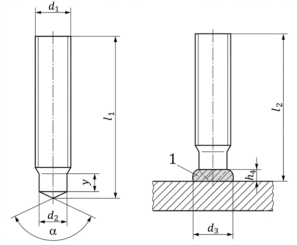
| d1 | M6 | M8 | M10 | M12 | M16 | M20 | M24 |
| d2 ±0.1 | 4.7 | 6.2 | 7.9 | 9.5 | 13.2 | 16.5 | 20 |
| d3 | 7 | 9 | 11.5 | 13.5 | 18 | 23 | 28 |
| h4 | 2.5 | 2.5 | 3 | 4 | 5 | 6 | 7 |
| y + 2P | 4 | 4 | 5 | 6 | 7.5 / 11 | 9 / 13 | 12 / 15 |
| α ±7° | 140° | 140° | 140° | 140° | 140° | 140° | 140° |
| l1 ±1b | (l2 + 2.0) | (l2 + 2.2) | (l2 + 2.4) | (l2 + 2.8) | (l2 + 3.6) | (l2 + 3.9) | (l2 + 4.7) |
| l2 | 15–100 | 15–100 | 15–100 | 20–100 | 25–100 | 30–100 | 40–100 |
all dimensions in mm
| Note | Description |
|---|---|
| a | The dimensions after the oblique stroke apply when ceramic ferrules are used. |
| b | Length l₁ applies to angle 140° only (without tolerance). |
| c | The given values are for guidance only. |
Dimensions Tolerances:
General dimensional tolerances for standard metric fasteners—including thread diameter, overall length, head diameter, head height/thickness, across flats, and washer dimensions—are available in our Standard Dimensional Tolerances for Common Metric Fasteners guide.
Certain product-specific features, such as drive recess dimensions, socket depth, countersink geometry, under-head radii, and other special characteristics, are governed by the applicable DIN or ISO product standard and may not included in this datasheet.
Download Technical Datasheets
| Material | Download |
|---|---|
| Steel | ⬇️ Download Datasheet |
| Stainless Steel A2 | ⬇️ Download Datasheet |
Material Characteristics and Recommended Applications
| Material | Characteristics | Typical Applications |
|---|---|---|
| Low Carbon Steel | High strength and economical | Heavy fabrication, machinery |
| Stainless Steel A2 (304) | Good corrosion resistance | Food processing, industrial equipment |
| Stainless Steel A4 (316) | Excellent corrosion resistance | Marine and chemical industries |
Technical Specifications
| Property | Specification |
|---|---|
| Product Type | Reduced Diameter Arc Weld Stud |
| Standard | ISO 13918 RD |
| Welding Process | Drawn Arc Stud Welding |
| Thread | Reduced Diameter Configuration (as applicable) |
| Installation | One-sided stud welding |
| Base Materials | Carbon Steel and Stainless Steel |
| Surface Finish | Plain, Zinc Plated (where applicable) |
| Typical Diameter Range | As per ISO 13918 |
| Weld End | Arc Welding Tip |
| Corrosion Resistance | Material dependent |
Applications
ISO 13918 RD Arc Weld Studs are widely used in:
- Heavy Machinery
- Industrial Equipment
- Structural Fabrication
- Railway Equipment
- Material Handling Systems
- Mining Equipment
- Power Generation
- Process Plants
- Steel Fabrication
- OEM Manufacturing
Advantages
- Designed in accordance with ISO 13918
- Optimised reduced diameter configuration
- Permanent metallurgical bond
- Eliminates drilling and tapping
- Excellent vibration resistance
- High static and dynamic strength
- Suitable for automated stud welding
- Fast installation
- Reliable weld consistency
- Suitable for industrial production
Installation Best Practices
Do
- Clean the base material before welding.
- Select the correct welding parameters for the stud diameter.
- Ensure proper grounding.
- Use recommended ferrules where required.
- Inspect completed welds visually and mechanically.
Don’t
- Weld onto contaminated surfaces.
- Use damaged studs.
- Operate with incorrect welding parameters.
- Ignore recommended projection settings.
- Install on unsuitable base material thickness.
Common Installation Problems & Solutions
| Problem | Possible Cause | Solution |
|---|---|---|
| Weak weld | Low welding current | Increase current |
| Porosity | Dirty workpiece | Clean base material |
| Misalignment | Gun not perpendicular | Correct gun position |
| Excessive spatter | Incorrect welding settings | Recalibrate equipment |
| Incomplete fusion | Poor grounding | Improve earth connection |
Frequently Asked Questions
What is an ISO 13918 RD weld stud?
An ISO 13918 RD weld stud is a reduced diameter stud designed for permanent attachment using the drawn arc stud welding process in accordance with ISO 13918.
How is an RD stud different from a PT stud?
PT studs feature a standard external metric thread for general-purpose mounting, whereas RD studs incorporate a reduced diameter configuration intended for specific application and welding requirements.
What welding process is used?
ISO 13918 RD studs are intended for drawn arc stud welding, not capacitor discharge welding.
What materials are available?
Standard materials include low carbon steel, A2 (304) stainless steel, and A4 (316) stainless steel.
Need Technical Assistance or a Quote?
Looking for pricing, samples, CAD drawings, or help selecting the right fastener? Our team can help you choose the correct product for your application.
📧 sales@horizonincindia.com | 📞 +91 80 4117 9152 | 💬 +91 99167 77262
Related Products
- ISO 13918 PT Internal Thread CD Weld Stud
- ISO 13918 IT Internal Thread Weld Stud
- ISO 13918 UD Capacitor Discharge Weld Stud
- Shear Connector Studs
Technical Disclaimer
The technical information, specifications, dimensions, mechanical properties, drawings, and performance data provided on this website are intended for general reference and engineering guidance only. Values shown are representative of products manufactured under normal production conditions and may vary depending on material grade, manufacturing tolerances, installation method, application, and operating environment.
While Horizon Inc. makes every reasonable effort to ensure the accuracy of the information provided, we make no warranties, express or implied, regarding its completeness, accuracy, or suitability for any particular purpose. Customers are responsible for verifying that the selected product is appropriate for their specific application and operating conditions. Where safety, structural integrity, or regulatory compliance is critical, independent engineering evaluation and product testing should be performed.
Horizon Inc. reserves the right to modify product specifications, dimensions, materials, and technical data without prior notice.
To the fullest extent permitted by applicable law, Horizon Inc. shall not be liable for any direct, indirect, incidental, consequential, or special damages arising from the use of, or reliance upon, the information contained on this website.
Copyright
© 2026 Horizon Inc. All Rights Reserved.
All content, product data, specifications, technical drawings, images, and documents published on this website are the property of Horizon Inc. and may not be reproduced, distributed, modified, or transmitted without prior written permission.